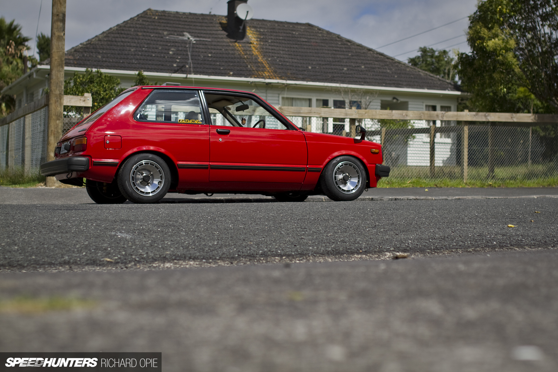
I’m not totally sure when, how and why I decided I’d cram the mechanicals from a vehicle distinctively not a KP61, into my KP61 shell. But I do know that when I embarked on the project I never anticipated just how in-depth this whole build was going to get.
Perhaps I underestimated the amount of work required to undertake such a project, but nonetheless the Starlet is progressing to the stage where the lifelines between all of the major components are requiring fabrication and install. While it’s all pretty interesting stuff, there’s definitely an element of lateral thinking required to make it all fit.
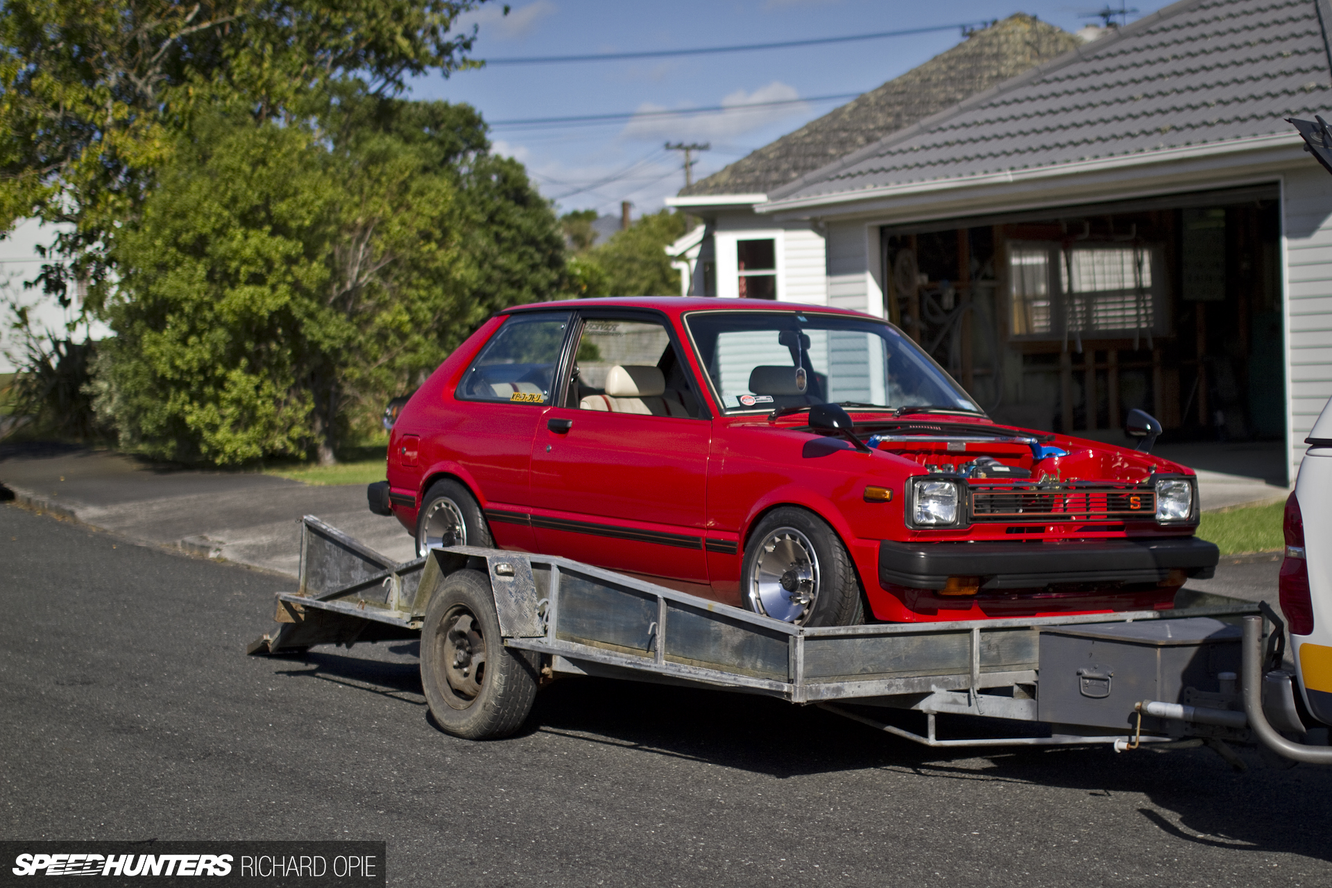
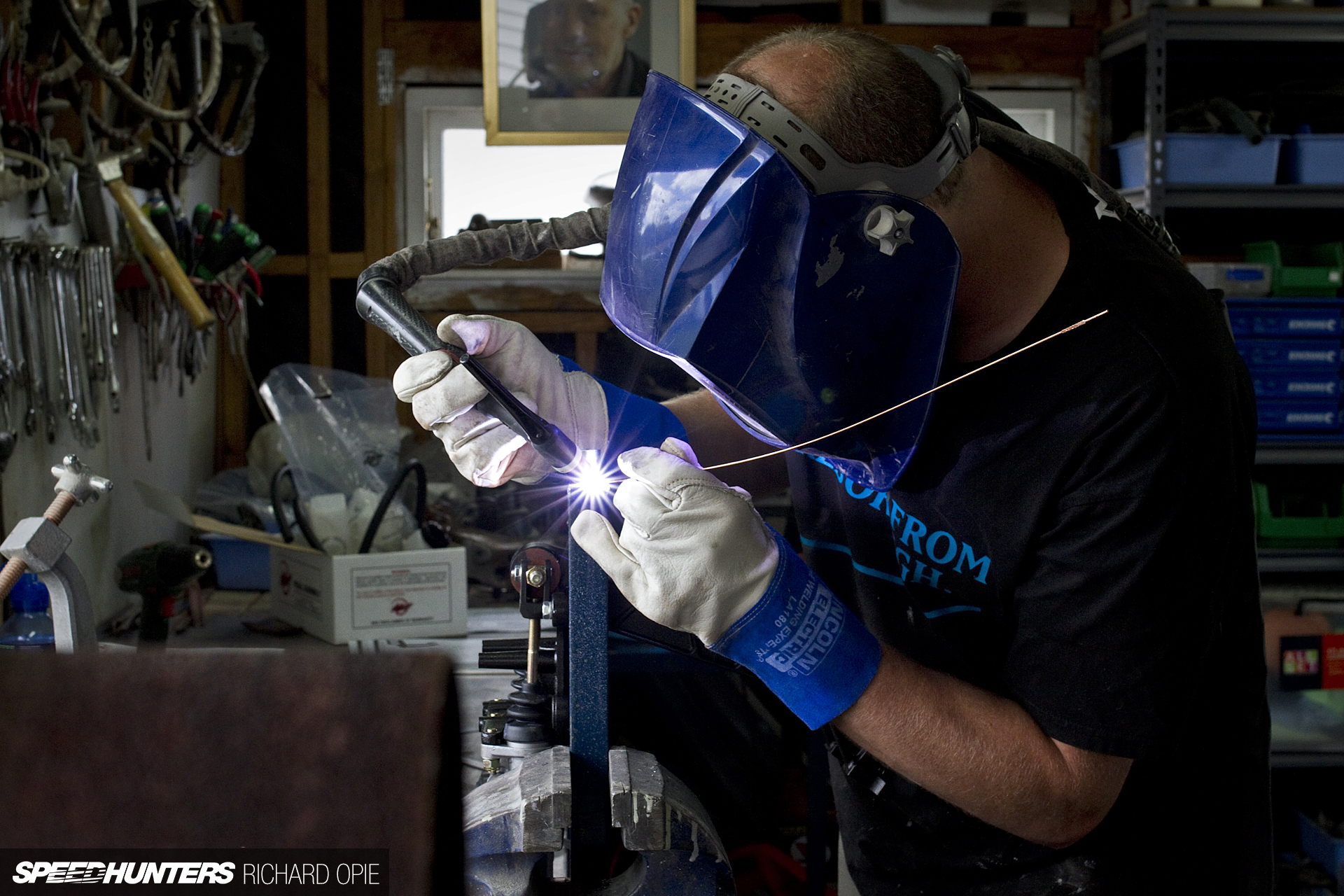
What better kind of day than a positively beautiful Saturday morning then, to get cracking on a couple of the final major fabrication tasks left on the car: the mounting of the new interior pedal box and a gearbox crossmember. The car was duly loaded on a trailer and off we trundled to our friendly neighbourhood Sheepers (you might remember him from his magical MS51 Crown creation) who was up for the challenge of solving the quandaries at hand.
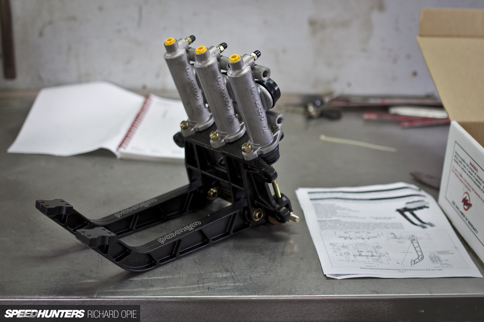
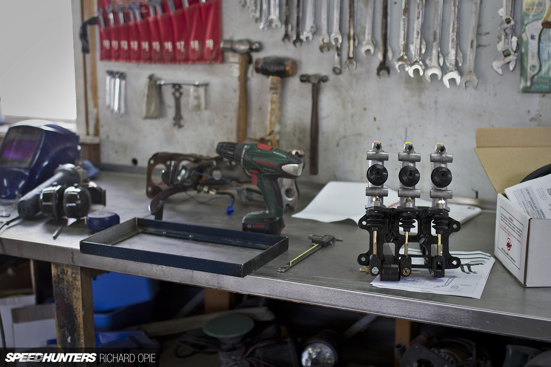
This was the culprit in question – a pretty basic Wilwood reverse swing type pedal box. I did initially consider a floor mount unit, but the tight dimensions of the KP61 cabin just would have made it an impractical choice. This particular unit has a 6.25:1 pedal ratio, and I’ve chosen 3/4-inch and 5/8-inch master cylinders for the front and rear circuits (calculated using the piston sizing) and a 3/4-inch master to suit the clutch.
The first step was to find out what we were dealing with dimensionally. A plan had already been roughed out for the mounting by this stage.
Stage one of the metalwork involved the construction of a steel frame which would mount the pedal box on a horizontal plane. All very simple – four mitred sections of right-angle steel TIG-welded together.
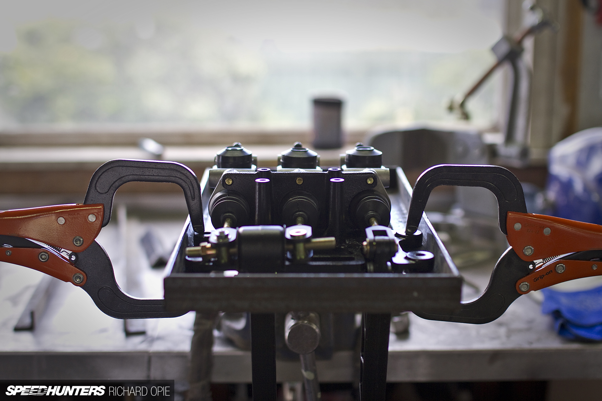
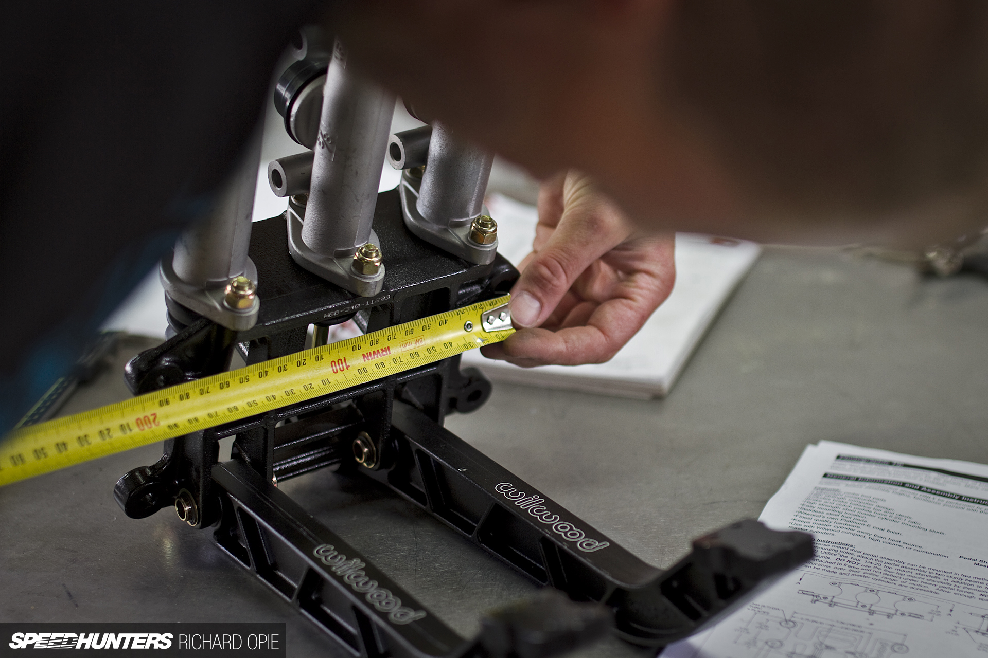
After a measurement from the firewall (and the first time around, we got this wrong….) the pedal box required clamping into place on the frame…
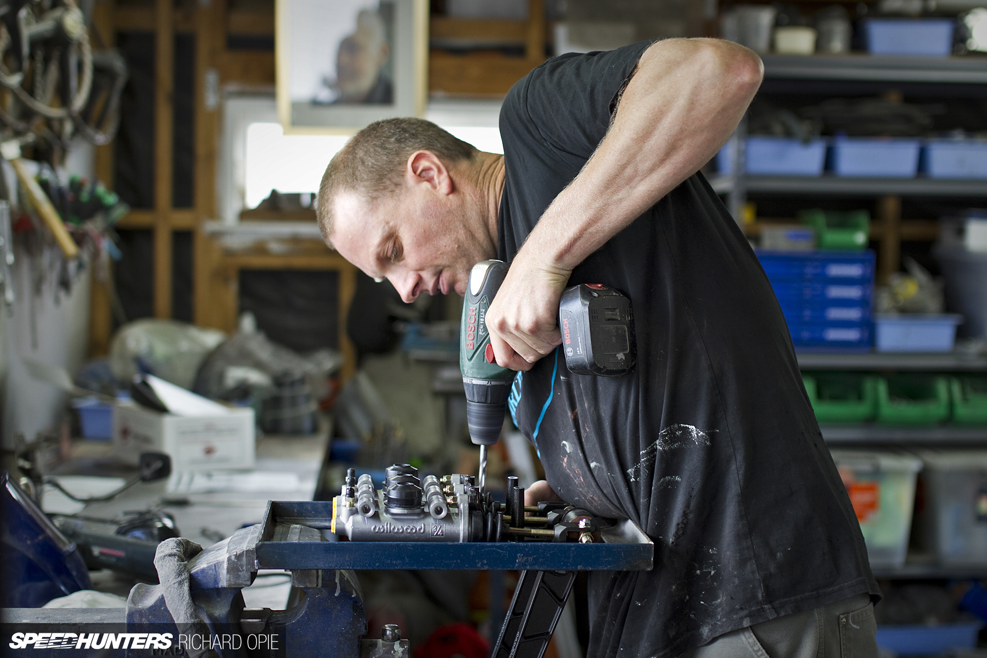
And mounting holes then drilled for the 4 M10-ish (whatever the equivalent is in an imperial size, 3/8-inch, I guess?) mounting lugs. This shot shows the locations being marked; the actual holes were drilled using a bench mount drill press.
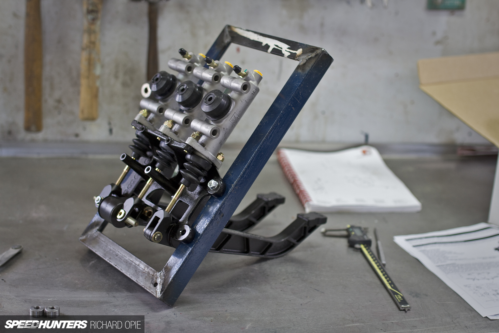
All mounted up, the frame and pedal box combo offered a pretty rigid construction due to the heavy gauge steel used. Too much flex when stomping hard on the brakes would present a less than ideal situation after all.
The forward edge of the unit mounts directly against the firewall, picking up two mounting points left behind by the original brake booster. Because the firewall surface isn’t totally flat across the distance this needed to mount against, so a couple of threaded lugs needed to be TIG-welded to the frame.
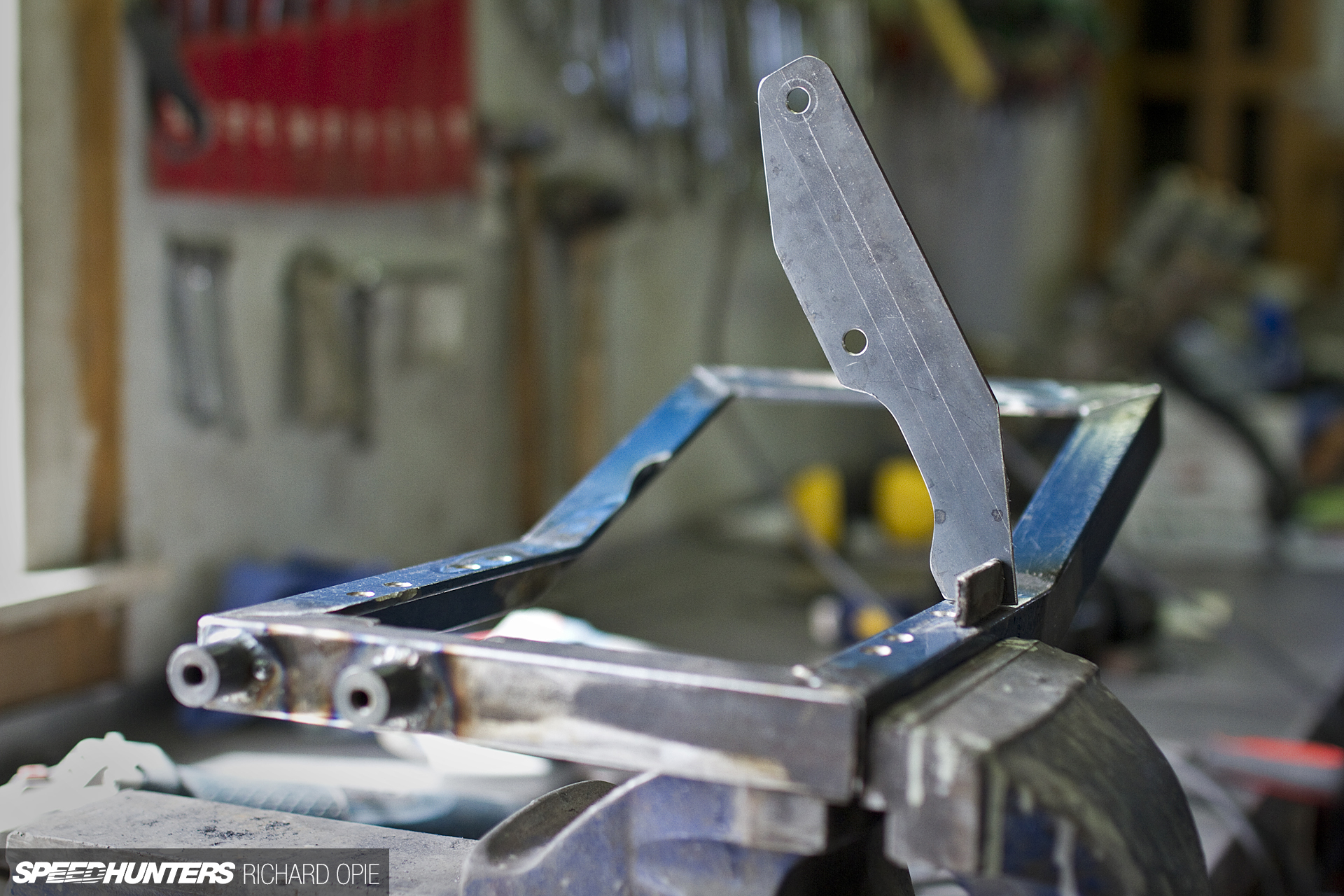
Visible here is the 20-degree angle bent into the frame. The framework serves a dual purpose; as well as securing the pedal box it also provides the mounting location for the steering column, so some careful measuring versus the original column mount was required in order to get the location right.
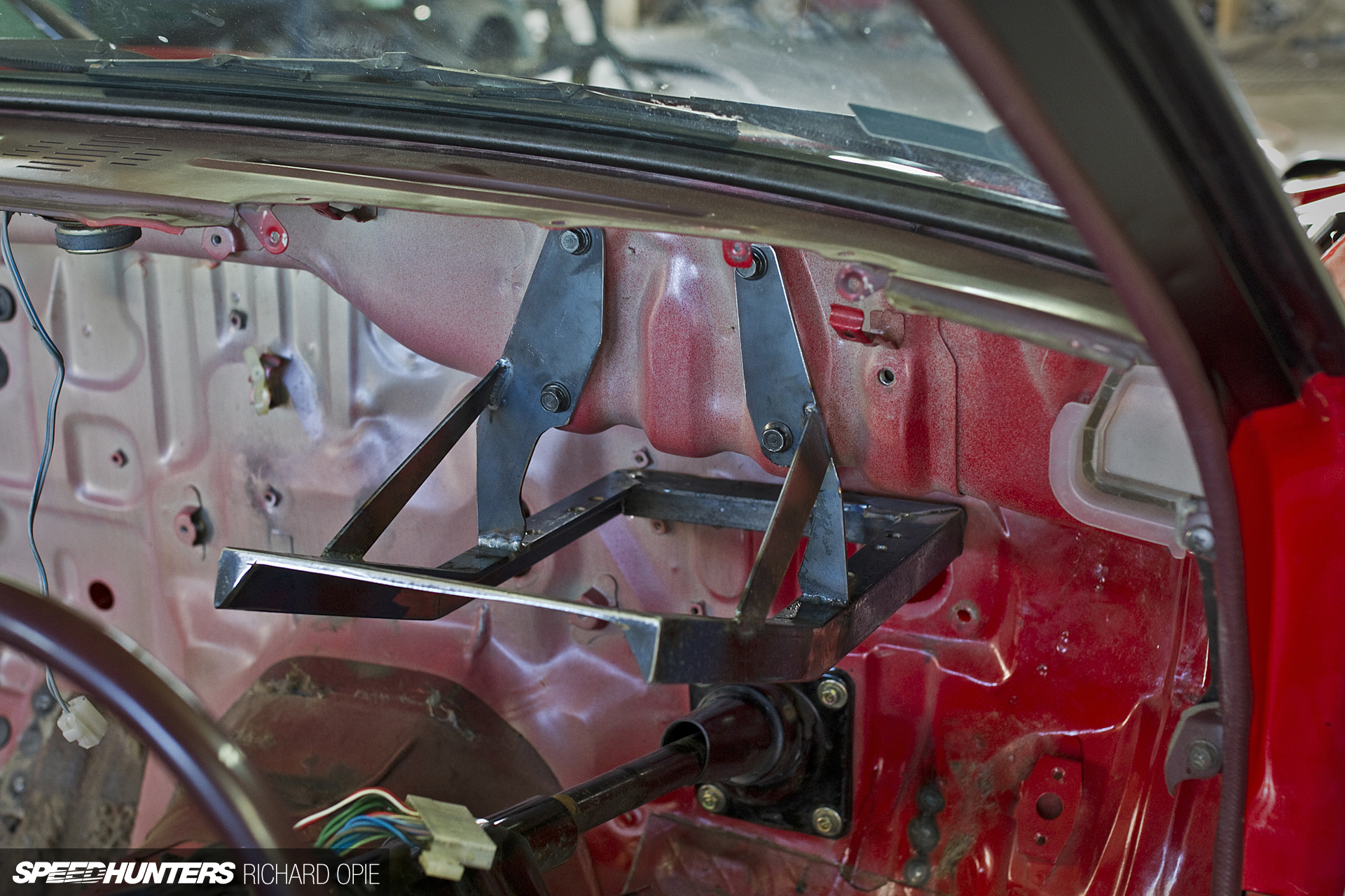
With each of the top stays TIG-welded and braced to the main structure it was time for a test fit, without the cylinders and reservoirs. Verdict? A perfect fit. Some clearancing was then required in order to fit the assembled pedal box and master cylinder unit.
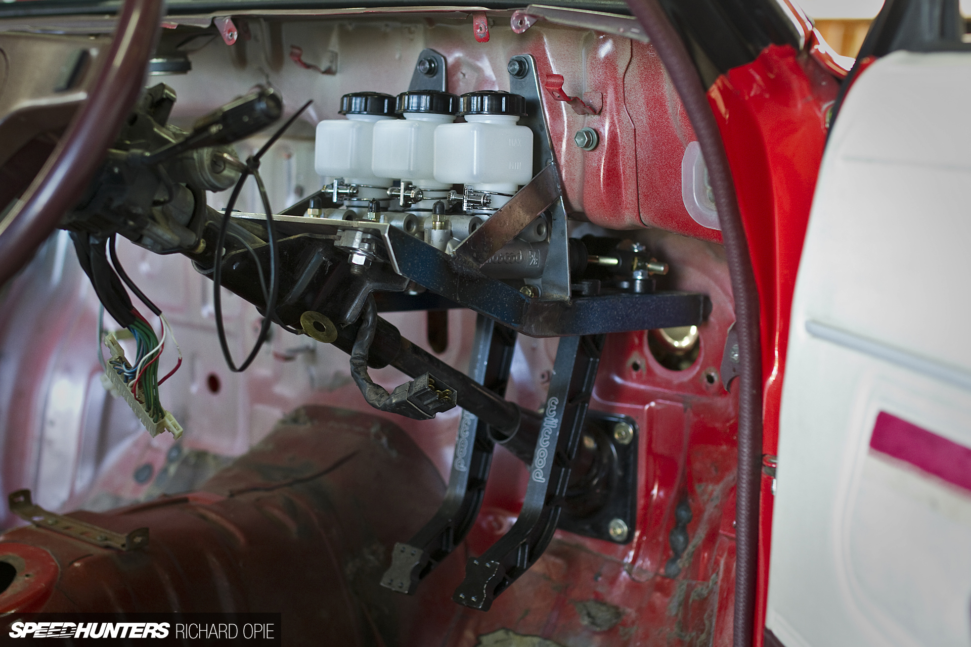
The net result (bar any painting or final touch up stuff) was as above. Note the steering column mounted in place. The whole structure is extremely rigid; with two of us trying to twist the assembled unit with all of our weight it wouldn’t budge, so should be suitable for some panic stops when I inevitably out-brake myself on track.
And yes, the reservoirs will be staying in that location beneath the dash. To refill or check the fluids it’s not as simple as it could be, but only a matter of six screws and they’re accessible. The logic behind it? Mounting them in the engine bay I just can’t get enough fall on feed hoses – another drawback of such tight confines in the KP61 shell.
[Cross]Members Only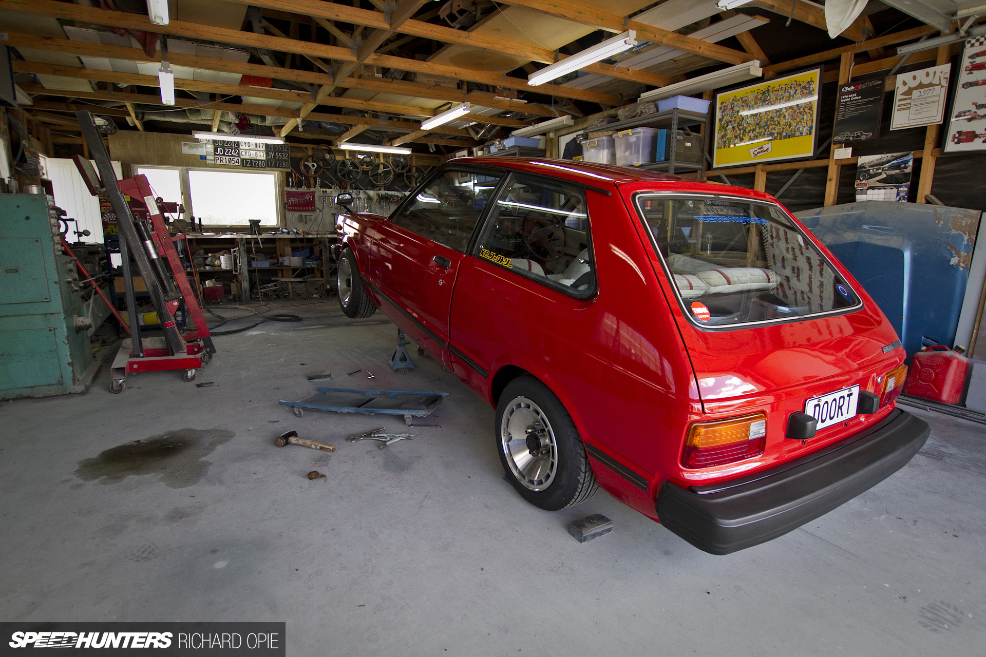
The pedal box consumed a full Saturday (delays for mugs of piping hot English Breakfast, then later for ice cold beer surely can’t be considered build time), so while the pedal box reached completion, the goal for the Sunday was to get the gearbox mounted securely to the floorpan.
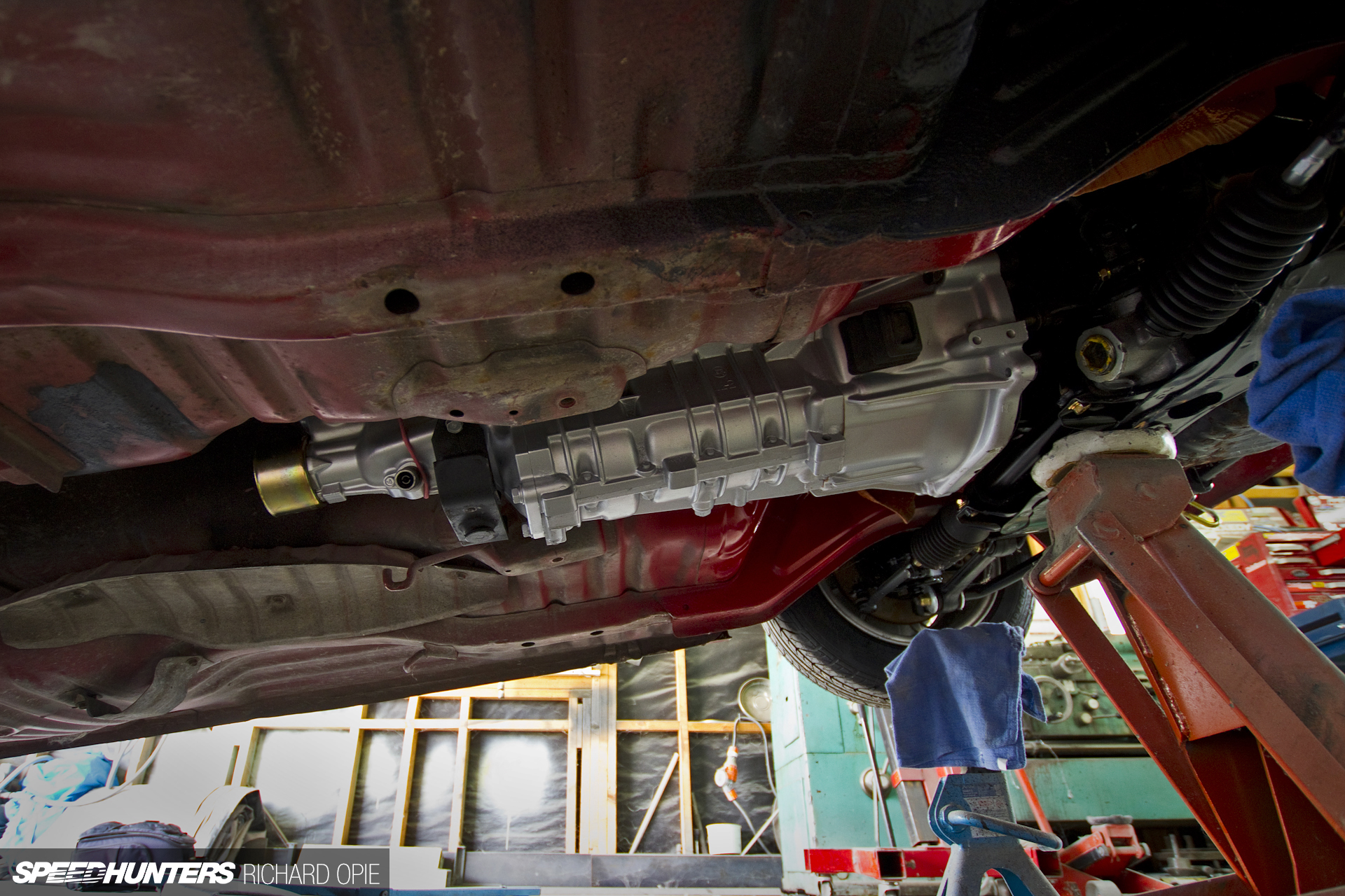
Here’s the state of play at the beginning. Using a length of cable, the gearbox was lifted into its suitable position. Visible here are the factory mounts on the floor, which are further forward than the Cusco mount which is just forward of the output shaft of the T50 gearbox.

Beginning with an OEM crossmember from a TE71 Levin, a jig of sorts was constructed which mapped out both the floorpan mounts as well as the gearbox mount. This in turn enable the forward facing ‘wings’ to be welded to the soon to be very non-OEM crossmember.
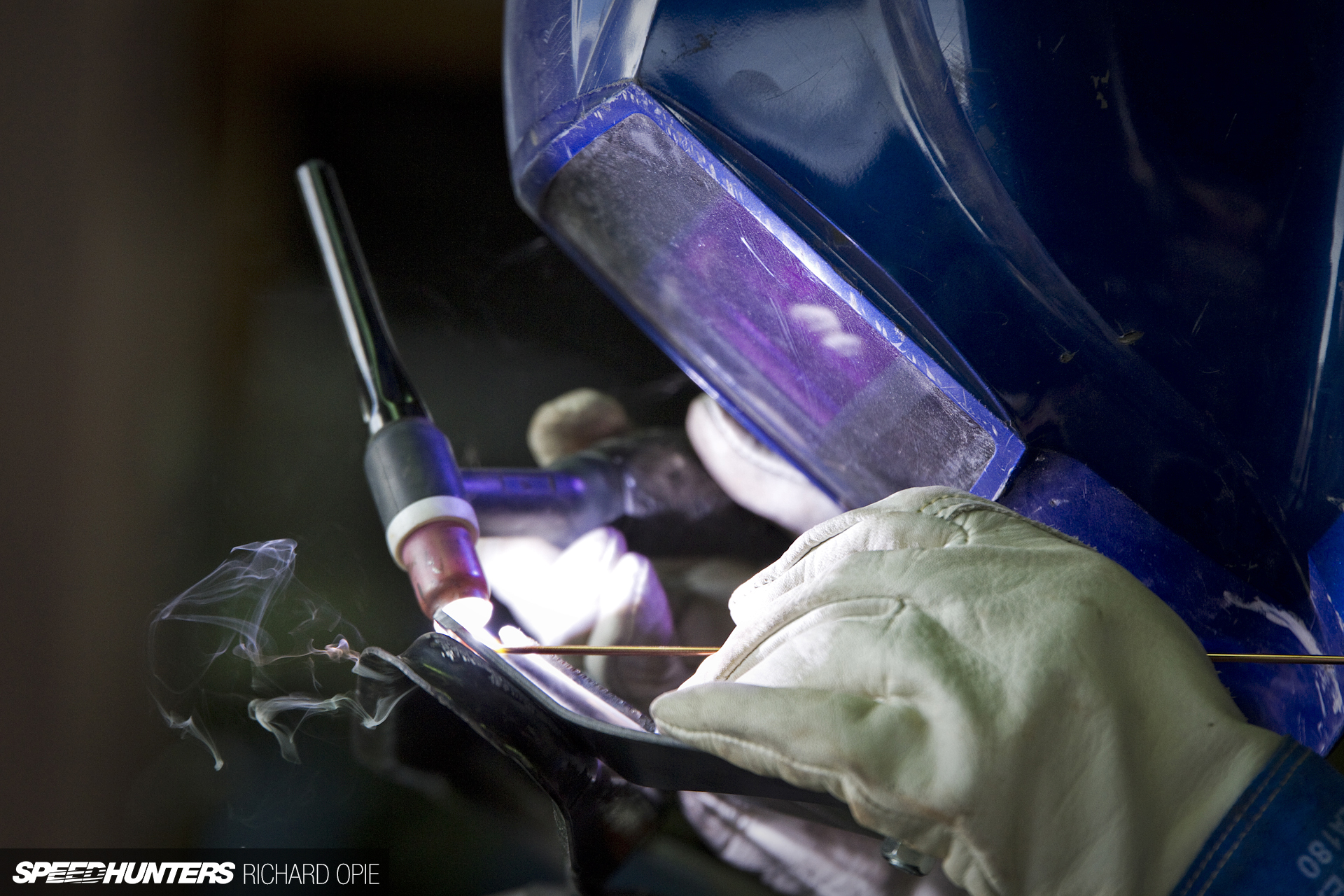
Here, the second of two extensions receives its final bead of weld, having been tacked on in place and offered up to the floorpan to ensure measurements were all within spec.

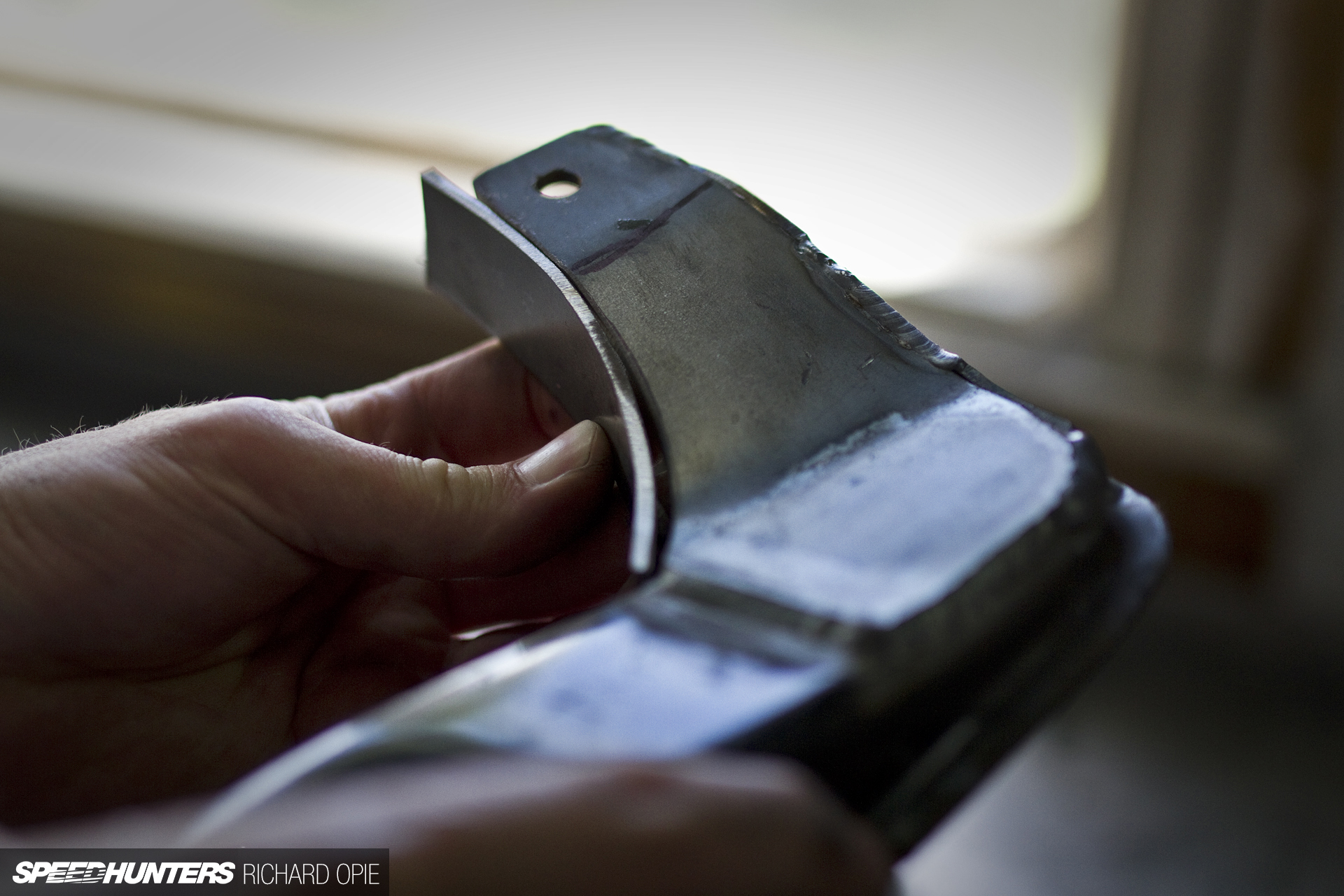
With the extensions in place, it was time to organise gusseting to ensure rigidity and strength; the gearbox crossmember has potential to take a bit of punishment as one of the lower hanging points on the underside of the car. Using cardboard templates, the gussets were traced onto steel, and cut out using the grinder, followed by a quick visual to confirm the fit was going to be acceptable.
Plenty of adjustments were made during this process, simply to obtain the most seamless fit possible in the given situation. That is, in a shed with some pieces of steel, a grinder and a welder, and the a clear absence of CAD software and laser cutting capabilities.
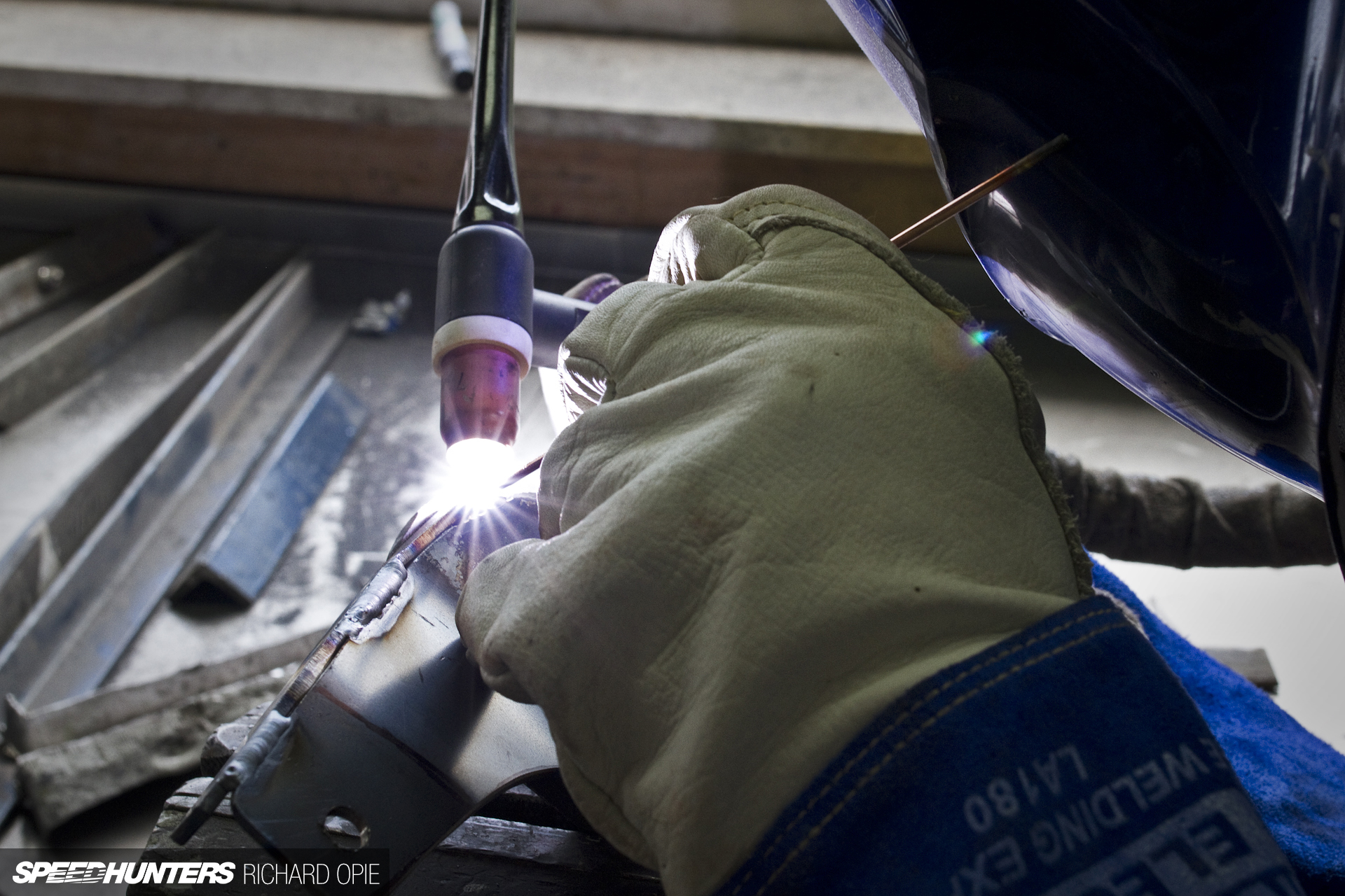
Satisfied the gussets were going to serve their purpose, it was time to weld (some more… always with the welding!).
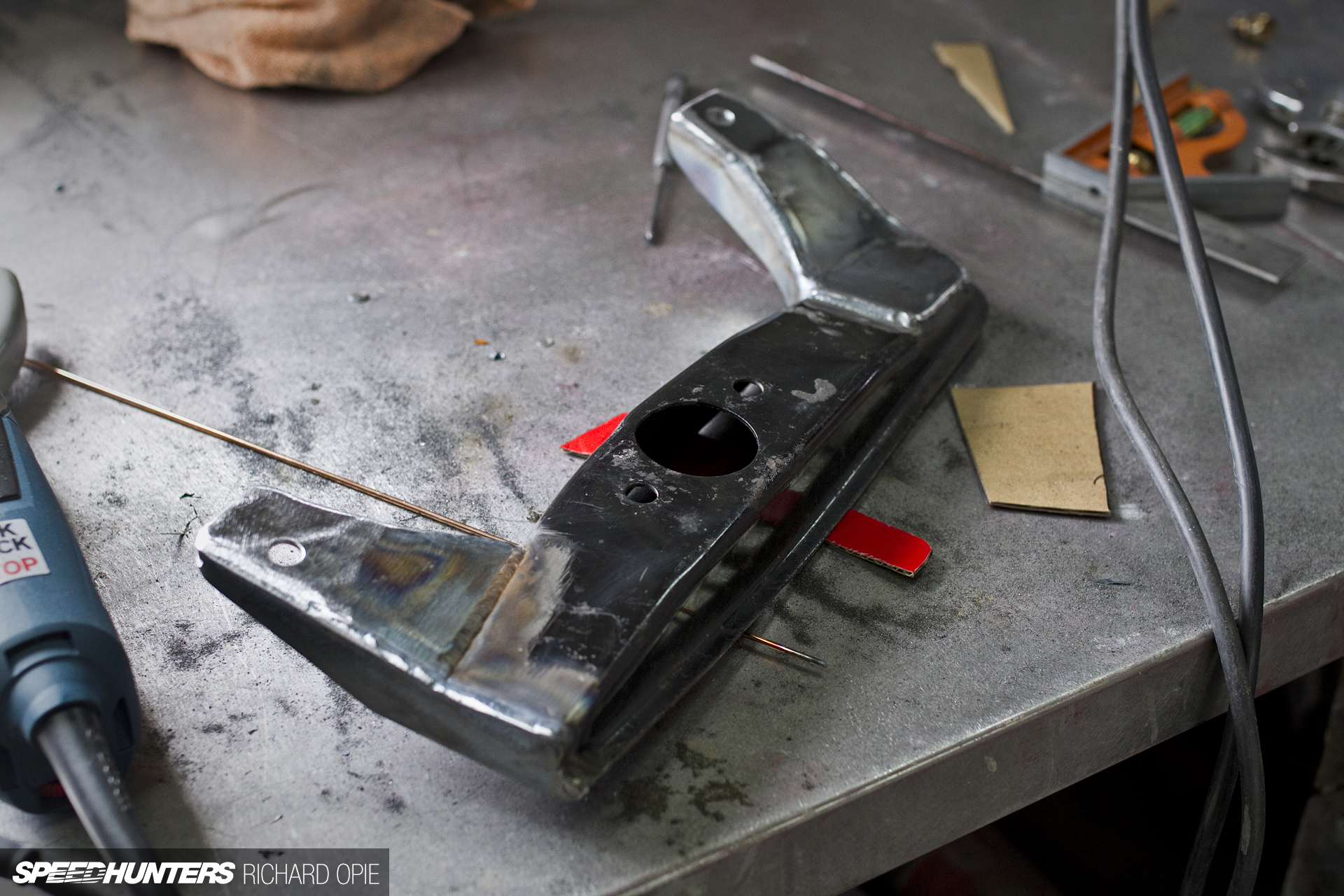
The completed unit resembled something like this – not pretty at this stage but the functionality side of things is well in check.
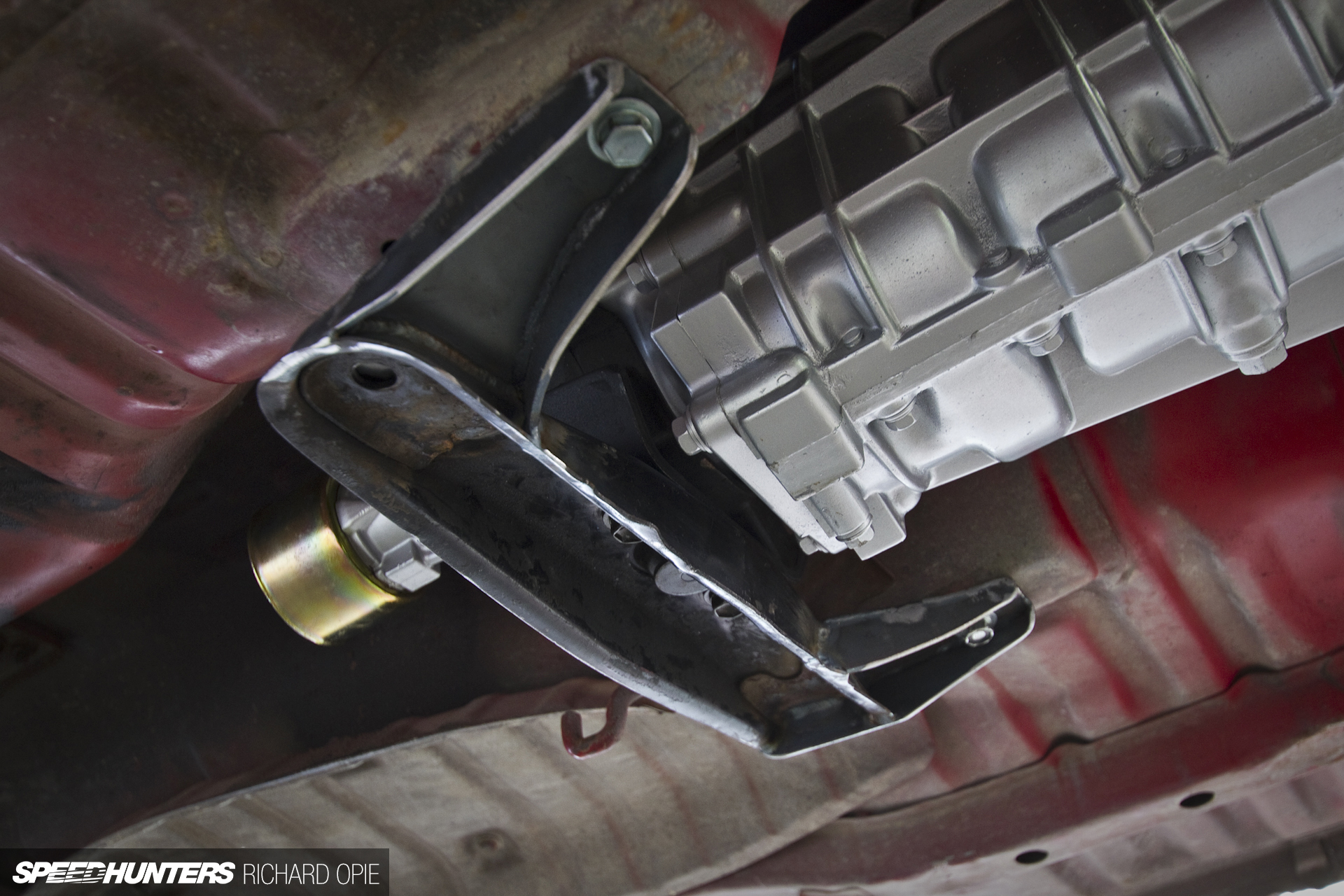
Of course, a final fitment was necessary and the job was done. There is one small task to complete on this, which is to plate the bottom section for additional strength. But given the engine and ‘box is going to need to all come out again, this will be completed at that stage, along with some minor modifications to engine mounts and a few other jobs before all of the fabricated parts are stripped and prepared for coating.
A Surge Of Motivation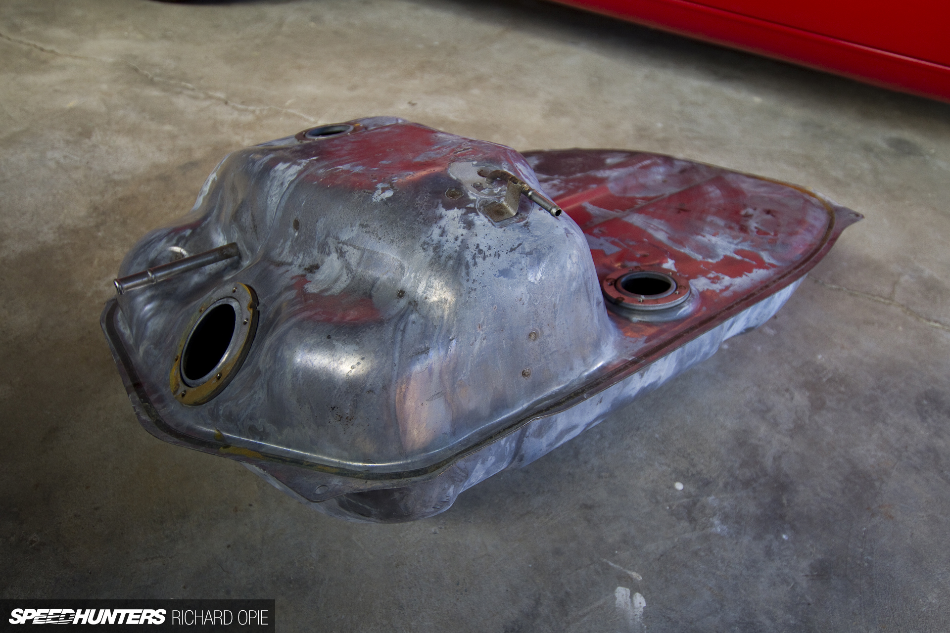
Mounting the engine, the gearbox, and even shortening the diff to suit the car – all of that could be considered the ‘fun’ bits of piecing together a project build. The not so fun bits? Putting the ‘services’ throughout the car. Likened to a building, this is the plumbing, the wiring, the fuel system – and this, possibly the single most boring photo ever posted on Speedhunters of the car’s original fuel tank post-acid dipping exemplifies the initial enthusiasm with which I approached the task of fuel.
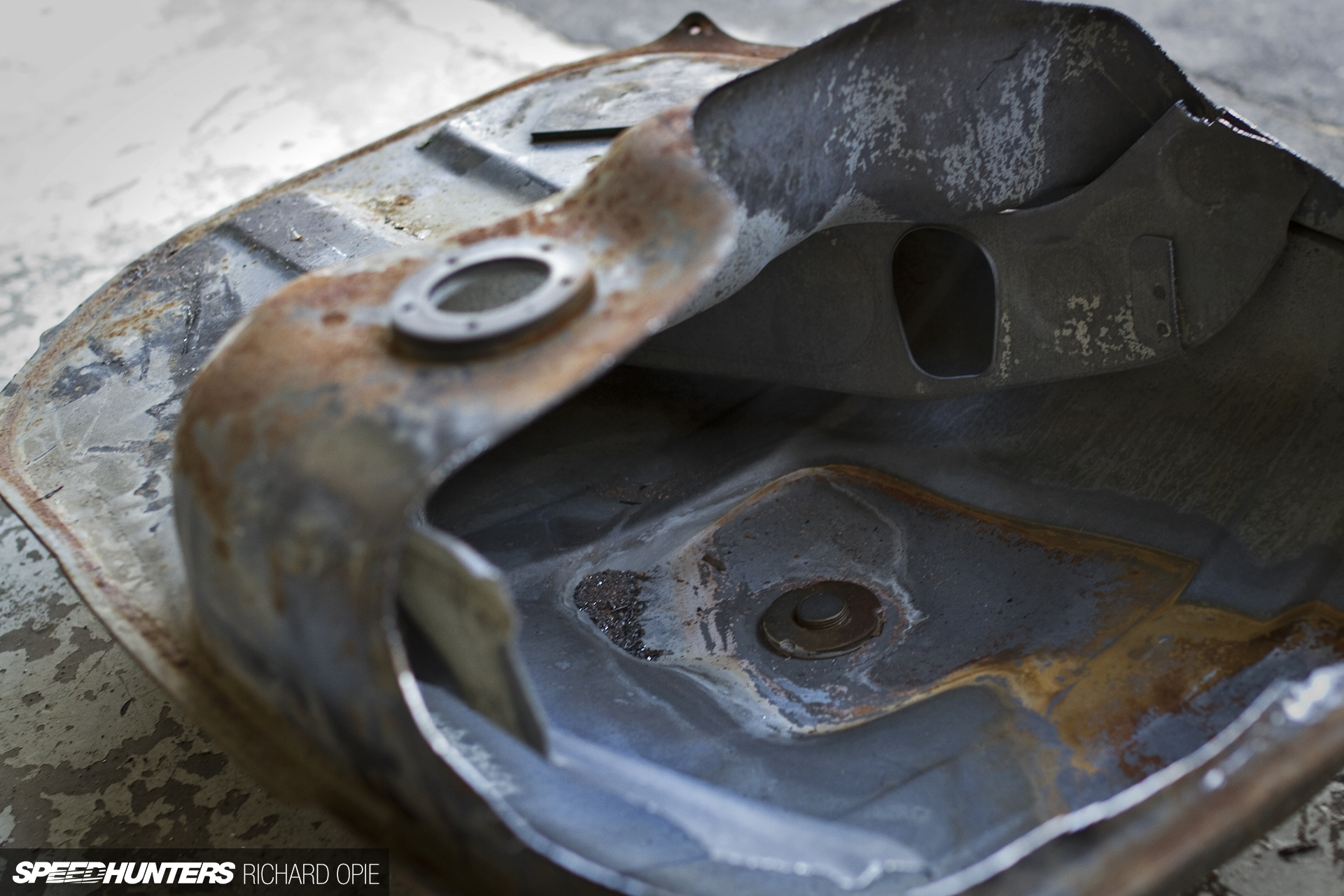
In a nutshell, the original tank, designed to suit a carburettor, wasn’t going to suit the fuel system in its standard state. That is to say, I wanted an in-tank type pump with no mucking around with lift pumps, surge tanks and main pumps all cluttering the underside of the car. So we needed to design and build a means of preventing fuel surge and accommodating an in-tank EFI-type fuel pump. This job was entrusted to Jon and Chris of Strange Workshop in Auckland, who also did some top-notch work on Taryn and Pedey’s Project Z a while back. The first step was to chop open a sacrificial tank, and work out what we were dealing with.

Once the location for the inbuilt surge compartment was ascertained, why not make it easy by cutting the required section out of the scrap fuel tank, transcribing the measurements onto the ‘good’ tank and marking it out ready for cutting.

Jon’s a deft hand with a grinder, taking on an ‘easy does it’ mantra. The old adage of measure twice, cut once, was adhered to as the grinder made short work of the factory steel tank.
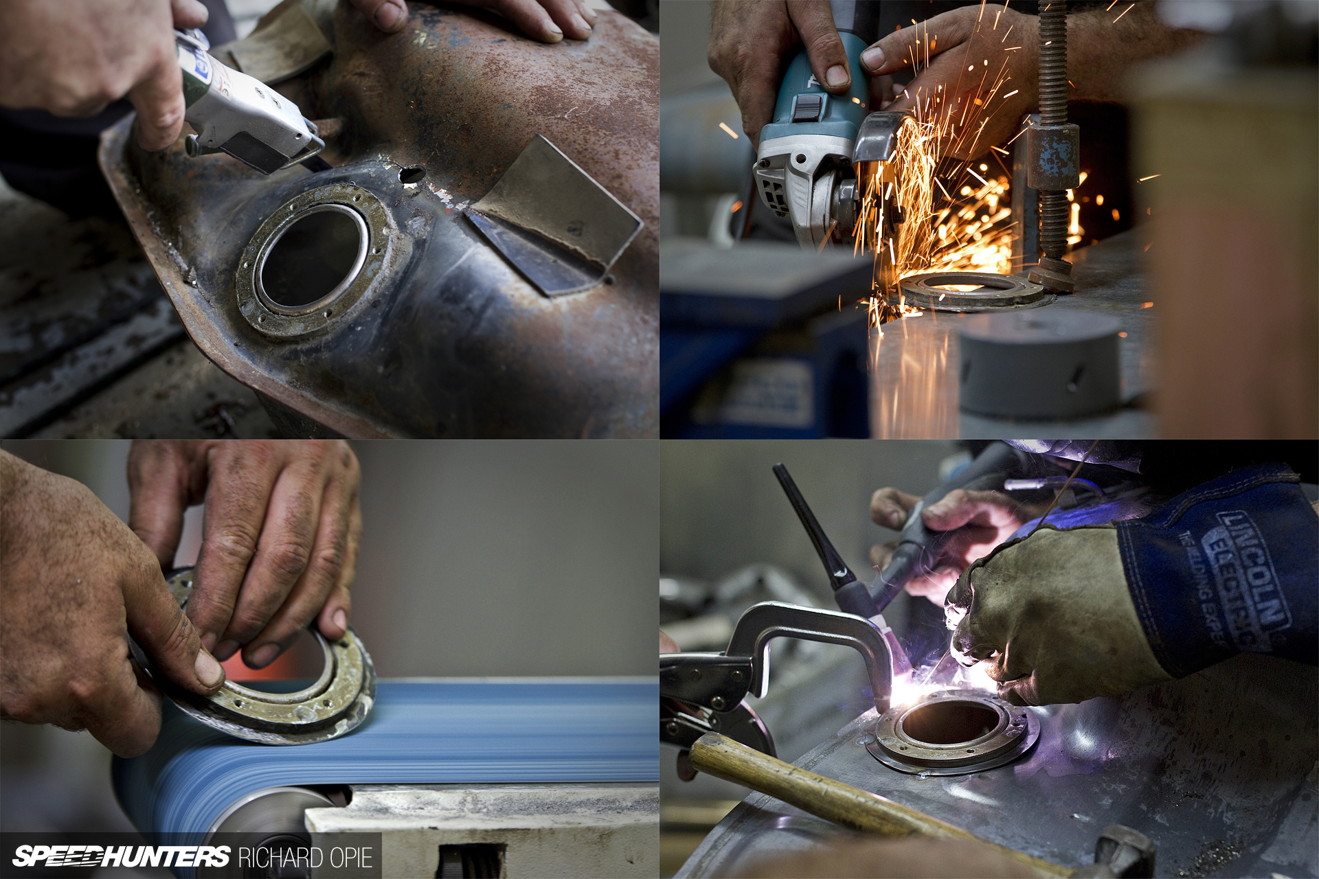
The scrap fuel tank also donated the flange which would accept the new fuel pump cradle; incidentally this flange originally served as the filler for the tank. The flange was chopped out, ground and linished to a round shape then welded in place on the tank where the original carb fuel lines would have been located.
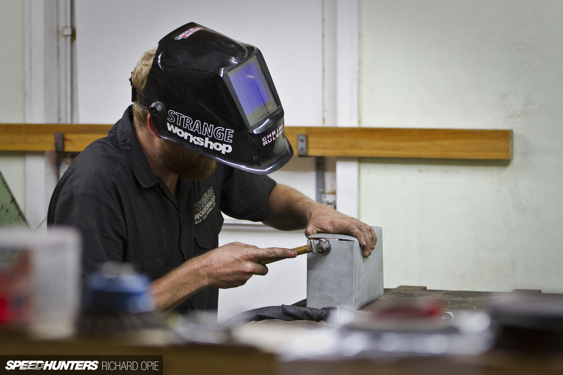
In the meantime, Chris cracked on with the surge tank, folding up a compartment of roughly 3-litres in capacity using some fresh sheet metal.
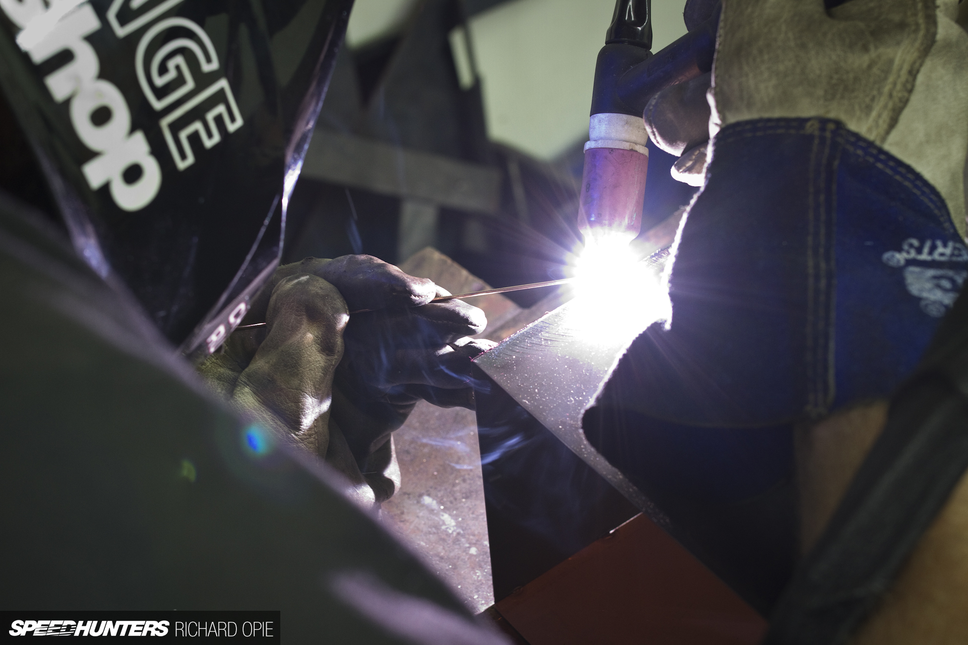
Step two was of course to TIG-weld the joins of the surge tank together.
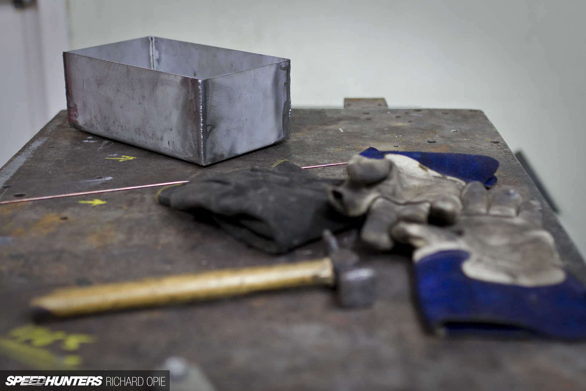
Then all of a sudden, a simple rectangular container is the net result, ready to be test fitted against the hacked up fuel tank.

The initial test fit involved ensuring the surge tank was sharing the same vertical plane as the fuel tank would when mounted beneath the car. The seam running around the circumference of the tank offered a simple reference.
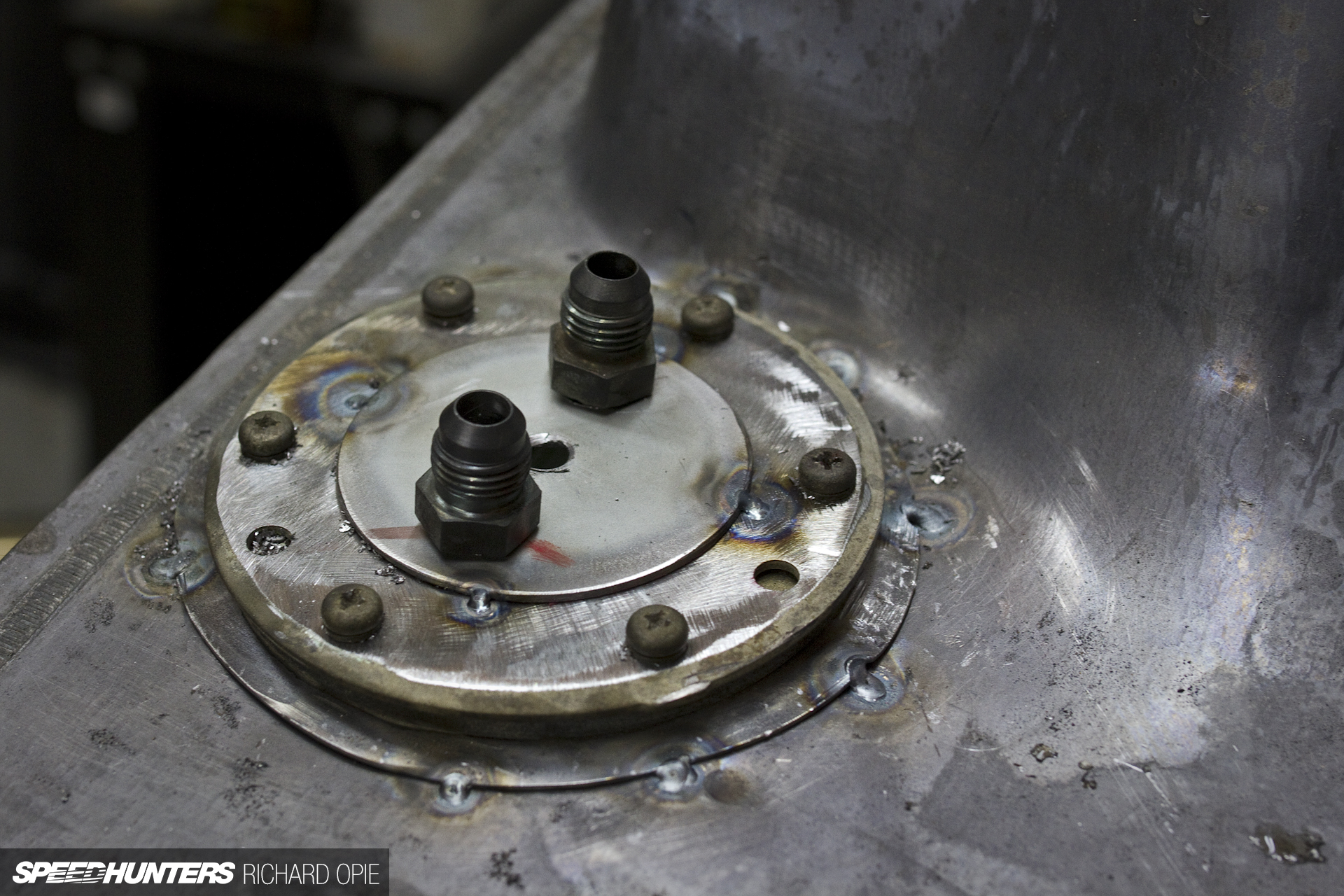
Tacked in, awaiting final welding the companion to the tank mounted flange began to take shape. Again born of a repurposed part, we elected to use a pair of -6AN fittings welded to steel feed and return lines below the tank with a steel cradle slung beneath accommodating the pump itself.
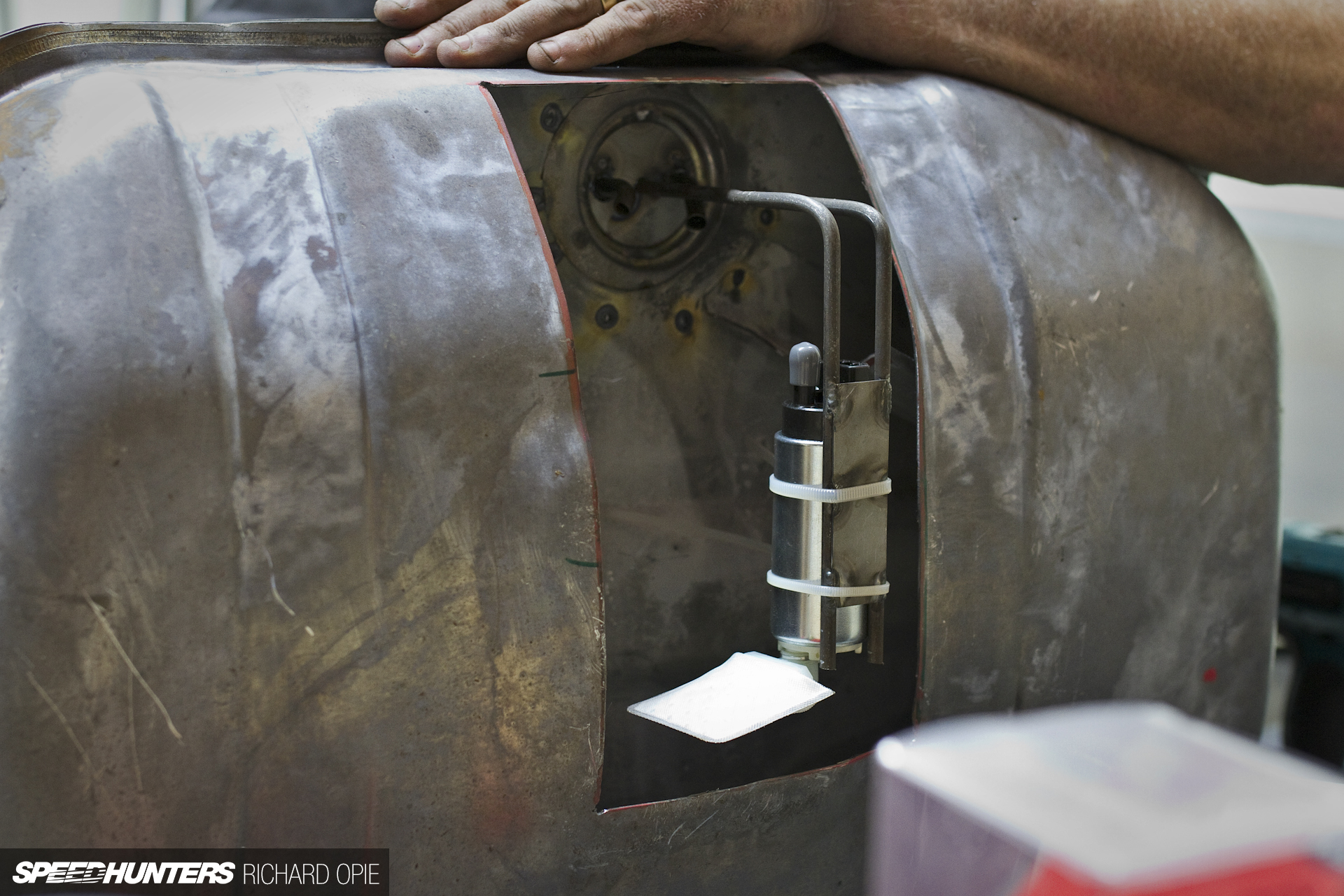
Without the surge tank installed, the assembly looks something like this – mounted on its side with ample fuel to draw from is a Walbro fuel pump with a flow capability exceeding that of the fuel requirements the 4A-GE might have.
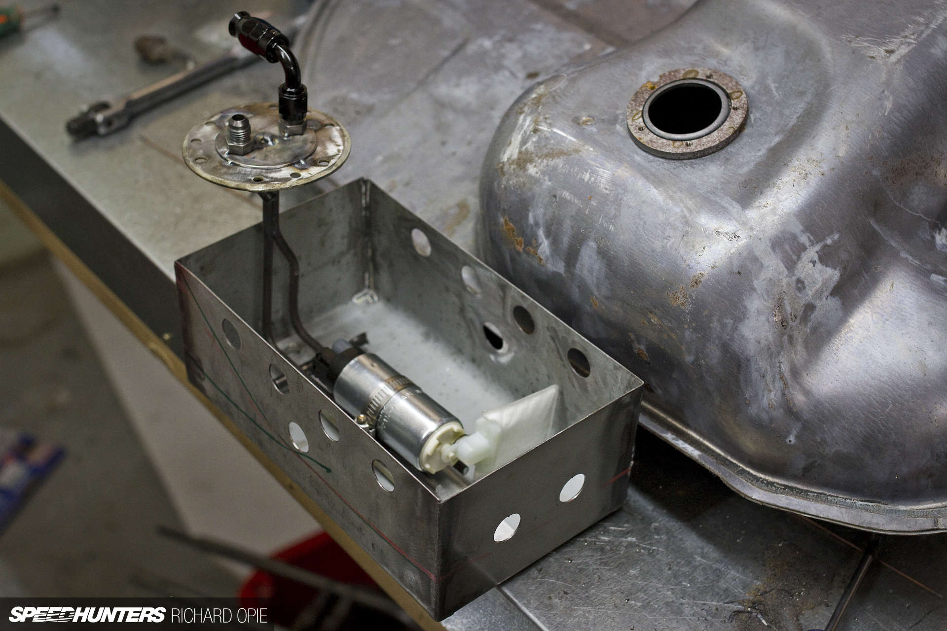
And out of the tank, the pump itself dummied up within the surge tank giving an indication of how the setup should work. As the walls of the surge tank protrude above the bottom level of the tank, several holes were required to permit the draining of fuel into this compartment, but sparing enough to trap fuel inside when levels get low to reduce possibility of fuel surge under cornering or acceleration. In theory, the fuel warning light will illuminate long before this is even getting near empty which I hope will provide enough of a safeguard to refuel.

It’s a time-hungry process. So the next time the fab shop hands you an invoice, before disputing the cost definitely take a moment to consider the time and expertise spent solving the problem you’ve presented them. In my case the tank is not completely finished (awaiting final welding, leak testing and refinishing), but Project KP61 is definitely taking some giant leaps forward thanks to some talented fabrication assistance.
Next on the list is to bend up a variety of brake hard lines from the pedal box to each corner of the car, and then to start tackling the wiring loom and solve a couple of niggly little problems, one of which is finding a suitable heater tap to mount beneath the dash. Either way, I’m motivated, and blessed with some of the best friends a car nut could want to crack on with getting this thing to the finish line!
Richard Opie
richy@speedhunters.com
Instagram: snoozinrichy